
Talk to an LS Engineer
Submit your information to get started, and we will route your request to our team for expert engineering support.
Technical Support
To help customers find answers faster, we publish a growing library of common technical questions. Review the Q&A below, or contact our engineers using the form above if you need support with your specific application.
A: Our cables are not tested by IEEE 383 & 1202 standards, however, we meet the UL Flame Exposure test listed in UL 1685.
A: Our 15kV EPR/CTS/PVC cables meet the following requirements:
- Single cables 1/0 AWG and larger
- Per UL 1685 (Flame exposure) and UL 2556 Method 1 vertical tray flame “For CT-USE” marking per UL 1072. (Exception IEEE 383 and 1202 flame test compliance).
- Multicore cable 2 AWG and larger
- Per UL 1685(Flame exposure) and UL 2556 Method 1 vertical tray flame “For CT-USE” marking per UL 1072 (Exception IEEE 383 and 1202 flame test compliance)
A: None of our MV UD (concentric neutral shield) cables meet both MV-105 and flame test CT-USE requirements. If MV-105 and CT-USE are needed, we can provide MV-105 cable (EPR/CTS [copper tape shield]/PVC jacket; Series G) However, the critical difference is that the metallic shield is not the same, thus MV-105 is not a proper alternate. The metallic shield is related to cable systems, so it should be engineered by user’s engineering division.
A:
Unilay and compressed strand are both types of cable strand constructions, but they differ in how the strands are arranged and how they're manufactured. Unilay stranding involves all layers of strands being twisted in the same direction, while compressed stranding involves compressing the strands together to reduce the overall diameter.
Unilay Stranding
Layout
- All layers of strands are twisted in the same direction, creating a more compact and lighter cable than a traditional concentric lay
Lay Length
- Each layer has the same lay length
Manufacturing
- Strands are typically twisted together into layers, then may be further processed to compact the overall structure
Advantages
- Offers a smaller diameter and lighter weight compared to traditional concentric lay.

Compressed Strand
Layout
- Similar to concentric lay, but the strands are squeezed together to reduce the overall diameter of the cable
Manufacturing
- Strands are first twisted together and then pressed or pulled through a die to reduce the diameter
Reduction in Diameter
- The diameter of a compressed strand is typically no more than 3% smaller than a non-compressed conductor of the same cross-sectional area
Advantages
- Provides a more compact and potentially stronger cable
Compressed strands are pressed down in size from 1 to 3%.
See 3rd from left below.

Combination Unilay Strand
Both layers have a common lay length and direction. Combination Unilay produces a round but softer alternative to compressed conductors. Compressed Combination Unilay provides an even smother surface but harder and with slightly less flexibility. Suitable for thin wall or semiconductor insulation.
In the LS catalog, there is a footnote for 8AWG conductors noting combination unilay-stranded, which means two different size strands are used to get a 3% reduction similar to compressed, but without compressing the strands.


Bottom-line, if you want to reduce the size of the conductors by 3%, you have two options; compress the conductor with a die, or use combination unilay with two different strand sizes to get the strands to fit together tighter without compressing them.
8AWG conductors are the only LS Cable products that use combination unilay-strand.
A: It’s not designed to be a current-carrying conductor. The main purpose is to reduce the electrical stress on insulation. But in fault conditions, it can act as a short circuit current carrying path and maximum capability depends on the calculation per ICEA P-45-482. (But it all depends on several factors being met at certain categories and criteria)
A: VLF testing according to the NETA and IEEE 400.2 is done after cable installation typically by a third party testing company at the cable installation site. This testing may be contracted between the general contractor and project owner.
LS Cable & System USA MV test procedures:
In general, there are three types of electrical tests that are performed during the service life of a medium voltage cable.
Installation Testing
This is a field test that is completed after installation but before splicing & termination. This test is performed to detect any possible damage caused while installing the cables.
Acceptance Testing
This test is completed after cables have been installed and all splices and termination have been completed, but before cables have been energized. This test primarily exposes faulty splices and terminations.
Maintenance Testing
This field test is made during the operating life of the cable. The test is conducted to determine the deterioration of the system and to check the serviceability life of the cables. After evaluating the information,
appropriate maintenance can be scheduled as necessary.
LS Cable & System USA cables are manufactured to high standards and tested rigorously in order to relieve end users of the burden of pre-installation testing. In normal situations, such testing is not necessary and the cable can be installed, as received, with confidence. However, pre-installation testing should be conducted if the customer specification requires it or if there is evidence of cable mishandling or damage.
Per IEEE Std 400 IEEE Guide for Field Testing and Evaluation of the Insulation of Shielded Power Cable Systems Rated 5 kV and Above, the recommended field test procedures for medium voltage cables (extruded dielectric) are:
IEEE 400.2 - IEEE Guide for Field Testing of Shielded Power Cable Systems Using Very Low Frequency (VLF)(less than 1 Hz)
IEEE 400.3 - IEEE Guide for Partial Discharge Testing of Shielded Power Cable Systems in a Field Environment
IEEE 400.4 - IEEE Guide for Field Testing of Shielded Power Cable Systems Rated 5 kV and Above with Damped Alternating Current (DAC) Voltage
Any of the three methods above are acceptable for installation, acceptance and maintenance testing. DC Withstand (Hi-Pot) Testing is not recommended for extruded dielectric cables, particularly for field-aged cables. Past studies have shown that the electrical life of the cable can be greatly reduced due to the additional electrical stresses caused by using a DC Hi-Pot Test. Further information on this subject is available in EPRI Report TR-101245 “Effect of DC Testing on Extruded Cross-Linked Polyethylene Insulated Cables”
Procedures from the MV Installation guide.pdf
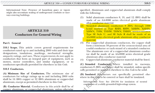
A: As a metal material, aluminum plays an essential role in different industries. It's flexibility, durability and light weightiness have made it a go-to option for many engineers, designers and manufacturers. However, not all aluminum types are the same. In particular, 1350 and 8000 aluminum alloys have distinctive properties that make them suitable for various functions.
A: LS Cable & System USA utilizes Chase BIH20ck in its strand filled products. See details below.

A: Yes, we can.
A: LS MV-105 products are UL Listed. UL Certificate of Compliance attached below.

A: LS does not have a low smoke, zero halogen (LSZH) compound for any of our cables. Also of note, UL nor ICEA offer this compound for MV cable.
A: Yes, we can manufacture LV tray cables similar to Belden, but with notable exceptions (see below):
A: Yes, our MV cables meet UL 1685 Flame Exposure test per UL 1685 as noted in our catalog.

A: In the image below, the red boxes indicate the industry specification that products are manufactured to. If there is a spec reference other than ULXXXX or ICEAXXXX, it is a non-standard product. A non-standard product may have different colors, markings, dimensions, compound, etc. per a customer's request or specification.

A: We do not offer MV-105 CTS with EPR jacket. EPR is an insulation material, not jacket material. Our Engineering team advises that a different EPR compound may be formulated for use as jacketing material (see below), but our current EPR compound is not and does not meet the standards we currently manufacture to (UL and ICEA). Of course, a customer may choose not to have it meet the standards we manufacture to, but it is unlikely that we source an additional jacket material unless there was a substantial upside.

We see many inquiries on MV URD cables where a customer wants MV-105 rated URD. These inquiries are usually in response to a competitor's spec where the EPR URD indicates:
- 105C continuous operating temperatures
- Can be listed by UL as Type MV-90 on special orders
- Improved temperature rating (Insulation system has been tested and qualified for operation at 105C continuous and 140C emergency operating temperature)
Our MV URD for EPR/CN/LLDPE indicates designed to operate continuously at a conductor temperature not exceeding:
- 105C for normal operation
- 140C for emergency overload
- 250C for short circuit
Overall, these products are rated with a continuous operating temperature not to exceed 105C and none of our competitor's spec (nor ours) indicate that the product will be market 'UL MV-105'. The only UL marking that any manufacturer can put on the print legends of these products is MV-90.
When comparing to competitor specs the way they are written can be confusing, but essentially, they provide the same product as LS.
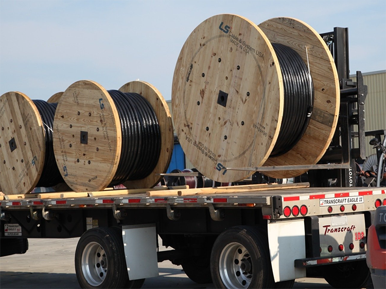
A: Yes, LS packages reels with a level 2 reel wrap which provides adequate protection for storing reels in outdoor or inclement weather (see below).
Typically, additional packaging materials are required for cable that will be stored outside. See NEMA WC 26, 2008 Edition, 2008 - BINATIONAL WIRE AND CABLE PACKAGING STANDARD
This standard covers uniform requirements for packaging electrical wire and cable and replaces the following NEMA/EEMAC standards
.png?width=341&height=366&name=eqa4(1).png)
.png?width=344&height=480&name=eqa4(2).png)
A: Coated copper is generally copper plated with another metal to improve performance; i.e. nickel plated copper (high temperature), silver plated copper (better electricals), etc. Our tin-plated copper drain wires per ASTM B33 prevent the galvanic reaction between copper drain wire and aluminum laminated tape.
A: Copper Tape Shield (CTS) is considered metallic shielding for our E8 / UL1072 (MV-105) cables. TC-ER is a UL listing for Tray Cables that have passed the additional "ER testing" for impact and crush resistance, usually attached to our PLTC/ITC, low voltage instrumentation, control and power cables (E1, E2 and E3). LS does not have a specific TC-ER UL listed cable that uses CTS. Many of our larger E8 cables can be used for tray cables (CT USE). TC-ER does not apply to CTS cables but the CTS cables 1/0AWG and larger can be installed in cable trays.
For Example:
![]()
A: Our VFD cables use a copper tape over XLPE conductors, so yes, we have the capability to make this cable. Tape thickness is 10mil vs. our standard 5mil. It is odd that there is no ground wire in contact with the shield, perhaps the metal tape is for rodent control? Please note that we are not currently quoting VFD cables at this time.